Introduction
The PhotonPix is an integrated module for photon counting based on a microchannel-plate photomultiplier tube (MCP-PMT). It comprises an MCP-PMT detector, high-voltage power suppliers, a constant fraction discriminator (CFD), cooling, overexposure and overheat protection circuits and a microcontroller.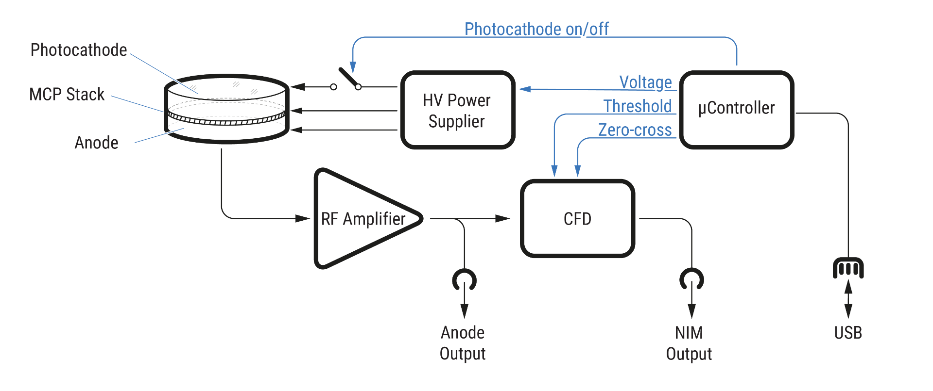
An MCP-PMT operation is supported by an integrated high-voltage (HV) power supply. The HV divider applies voltages to three main points: the photocathode, the MCP stack and the anode. The photocathode can be quickly switched on or off by the overexposure protection circuit or by user command. The output of the anode is connected to a fast RF amplifier. The output signal of the amplifier is split by a fast active signal splitter. One of these signals is available to the user via 50Ω matched SMA connector marked as “Anode”. The second of the signals is fed into a CFD. The output of the discriminator is a logical current signal of 20mA that on 50Ω load results in -1/2V amplitude.
The microcontroller enables the control HV power supplier. The user can adjust the MCP voltage to optimize the parameters for measurement conditions. The voltage at the MCP stack is required to be stable and shall be applied slowly. Practically the increase from zero to the working voltage level takes up to five seconds. The photocathode is supplied independently and can be switched on or off within hundreds of milliseconds timescale with the software. However, the protection circuit has an integration time of 1ms. This independent scheme is crucial to implement built-in overcurrent protection. Additionally, it is a convenient user-available feature to temporarily block the photocathode for the maintenance or adjustments of the experimental setup.
CFD requires setting up threshold and zero-crossing voltages. Those values are fully defined by the user depending on expected photon flux.
Output signals
The output signal oscillogram is shown in figure below. The upper (red line) depicts an amplified analog anode output signal. The lower trace (green line) shows corresponding logical NIM signal. There is a delay of about 2ns between anode and NIM caused by CFD logical elements. Please note that there is a finite dead-time of the CFD.
At the time between 14-18ns there are three pulses visible in the analog channel that yield only two logical pulses at the output. This is due to the finite electronic dead-time of the CFD.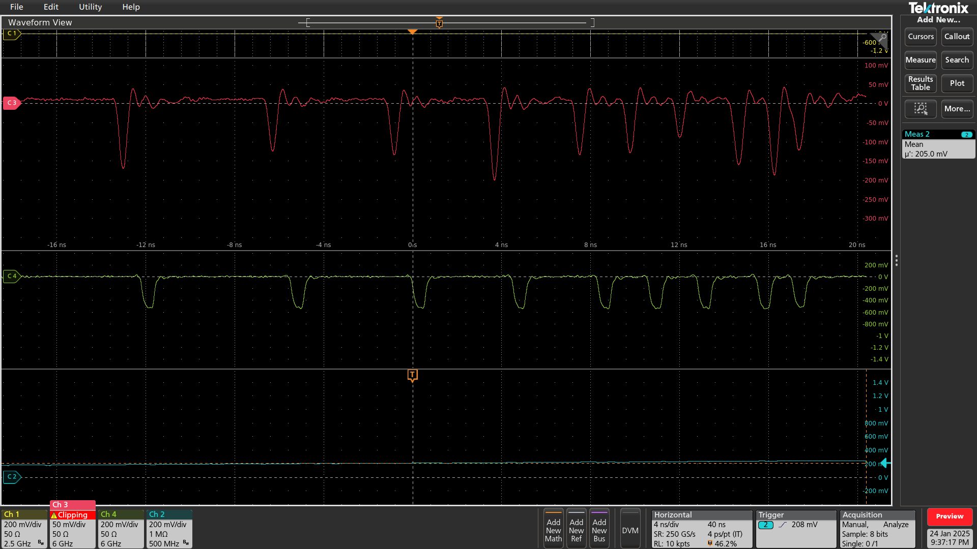
To visualize and measure the dead time of the PhotonPix a longer signal acquisition was performed. In the figure below the oscilloscope was triggered by NIM signal and both traced were integrated over several seconds. As one can see there is a time range of 1.6ns after the leading edge of NIM signal where no second pulse appears. This shows the dead time of the CFD.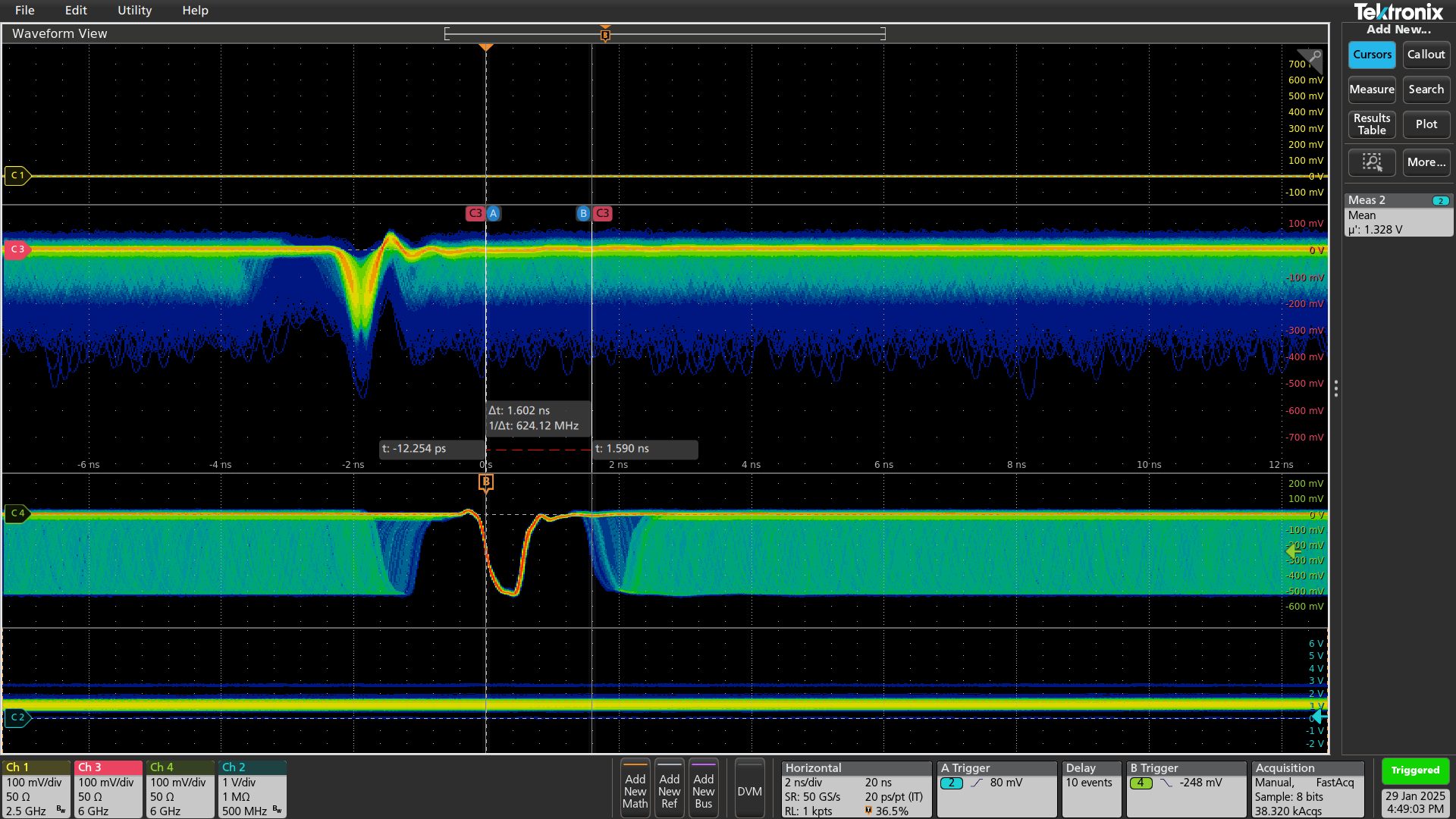
Before you begin
Safety measures
Before starting to use PhotonPix please read carefully the measures listed in this section. PhotonPix is extremely sensitive equipment and shall be handled with care to avoid detector damage.
Warning
Always use protective cap during storage
Even without high voltage applied the photocathode can be damaged. Do not expose photocathode to bright light during storage.
There is overexposure protection built into controlling electronics. This protection circuit counts the pulses every 1ms and disables high-voltage applied to the photocathode once counts exceed 110K, corresponding to 110MHz of overall count-rate. However strong fluctuations in the light flux like a photo flash can be faster than integration period of 1ms thus damaging the photocathode.
Warning
Avoid strong illumination changes
During the measurement apply measures to avoid overexposure.
To avoid overexposure, make sure the illumination conditions are under your control as much as can be reached. Please note, the fact that one does not see the light does not imply there is no light. The radiation can include an invisible part of light spectra, the sensitivity of the PhotonPix is much higher than bare eye.
Warning
Control the surrounding
Perform detector operation only in the controlled illumination environment.
The detector is cooled by the Peltier thermal element that requires secondary cooling to dissipate heat. The voltage to the Peltier element is applied when PhotonPix is connected to the power source. Non-properly running secondary cooling may result in overheating and detector damage. The alarm signal is triggered once one of the conditions met: (1) detector temperature exceeds 40°C; (2) electronics temperature exceeds 60°C. The alarm also disables Peltier power.
Warning
Avoid overheating
Connect the cooling and make sure the coolant liquid is circulating before applying main power.
Starting the first measurement
Please use the following check list to get started with the detector:
- Cooling is connected and a coolant liquid is circulating.
- The photocathode is closed, and/or any external light sources are off.
- The detector is connected to the computer and is recognized in the software.
- The main power is connected.
Once all the above points are satisfied one can apply the main voltage.
In the box
PhotonPix is shipped with everything one needs to start counting photons.
Hardware
PhotonPix is an integrated single photon counting module build on microchannel-plate based photomultiplier tube (MCP-PMT). To grant robust and fast acquisition the module integrates the following:
- MCP-PMT high-voltage power supply.
- Overexposure and overheat protection circuits.
- Communication micro-controller.
- Integrated Peltier cooling.
- Power supply modules for every element accepting a single external voltage.
- Constant-fraction discriminator (CFD).
Features

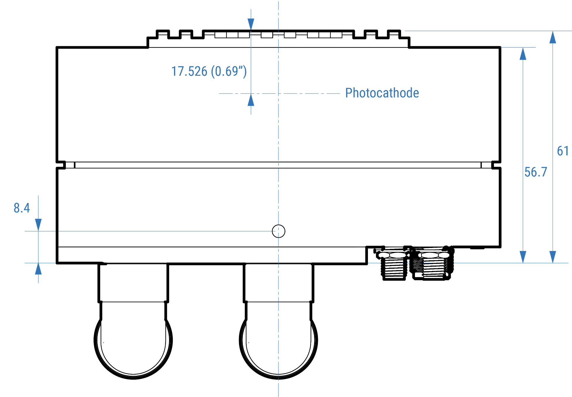
The optical input is a standard C-Mount with 1-32 UN 2A ANSI B.1 (Ø1 inch, 32 thread per inch). The detector is protected by the anti-reflection coated glass. The active detector area is Ø8mm.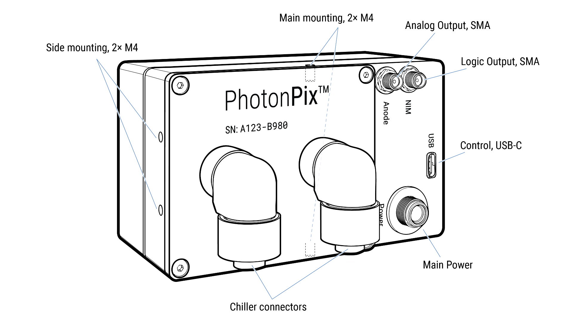
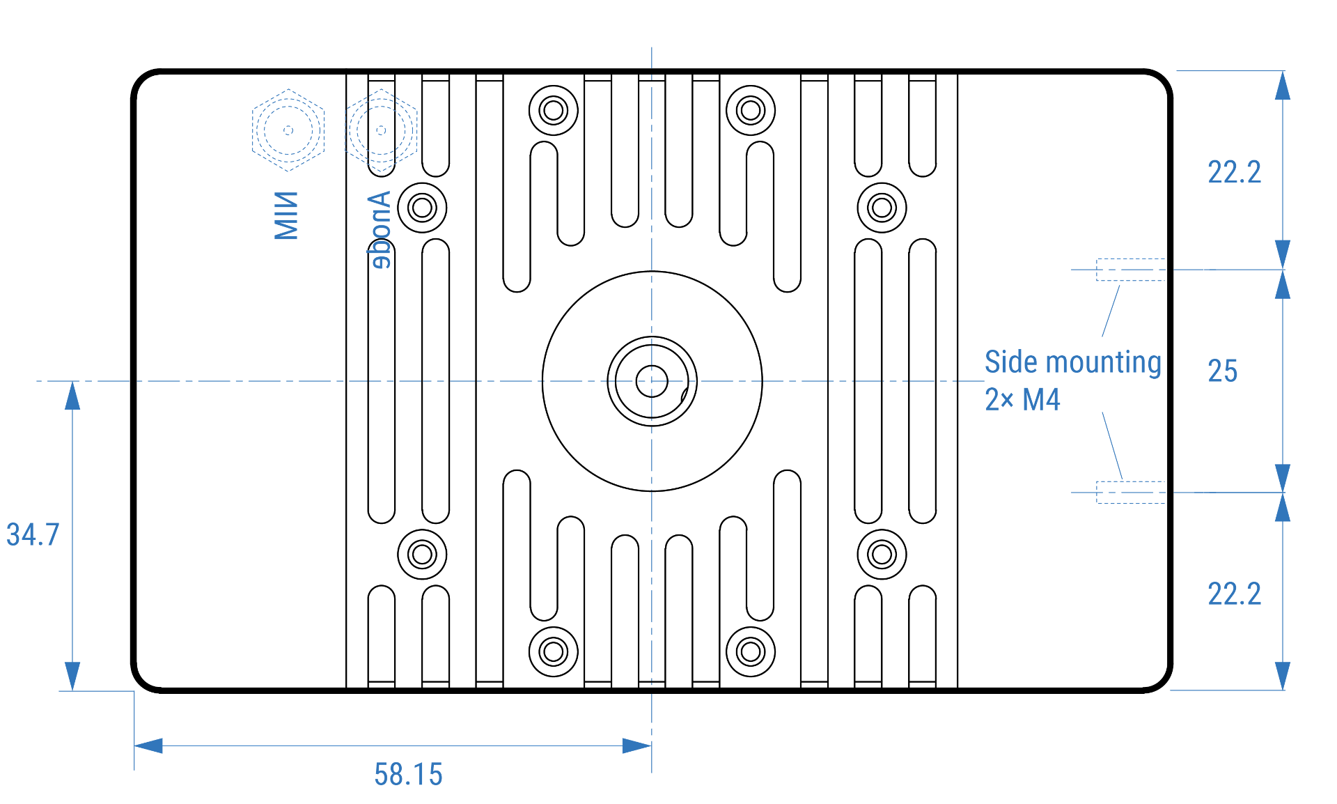
The housing has 4 mounting holes: two on the shorter side, one on top and one on the bottom side. All the holes have M4 thread suitable for mounting to optical setup. The pair of side holes is 25mm apart matching a standard distance of mounting holes of optical table or bread board. Depending on your setup the device can be mounted with the hole on top or at the bottom.
There are two chiller tubing connectors. They must be connected to the chiller before applying main power.
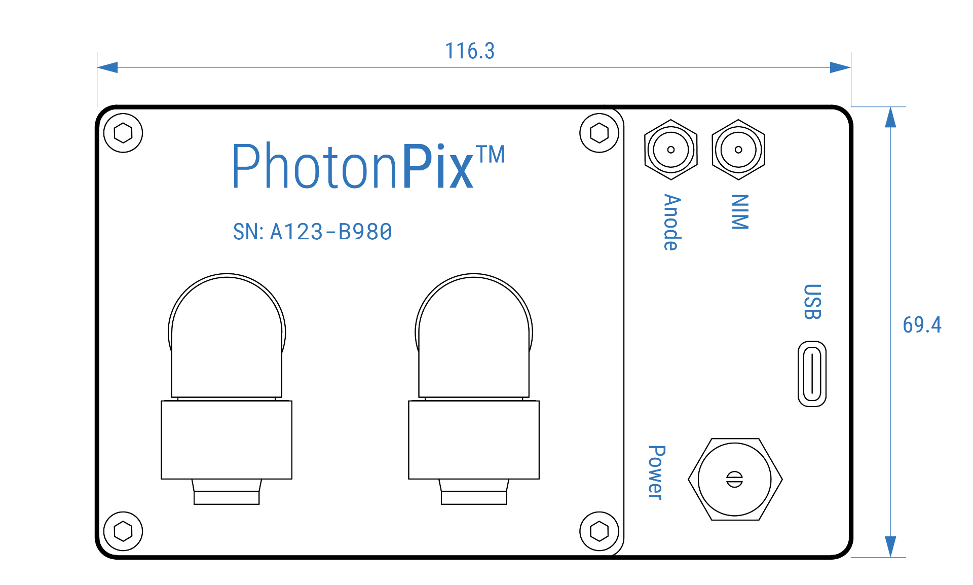
Two signal outputs are available via female SMA connectors: analog and logical. Analog output is connected directly to the amplified anode signal before CFD. This output enables monitoring of signal amplitude and frequency with oscilloscope. The second NIM logic output is a main signal source to be used with timing electronics.
USB-C control port shall be connected to the computer for proper operation. If there is no voltage applied with USB nor the HV neither Peltier power will be applied.
Mechanical drawings
All sizes are in mm (inches “). All the mounting holes are in the same plane 8.4mm from the back side.
Power consumption
The module accepts any direct current voltage in a range of 5-12V. Depending on applied voltage different detector temperature is set and consequently different thermal dark count is reachable. The power consumption of electronics is 3.5W excluding Peltier thermal element. The consumption and corresponding thermal noise of red-extended Photonis HiQE-Green photocathode are summarized in the table below.
| Peltier voltage, V | Current, A | Power, W | Thermal noise, Hz |
|---|---|---|---|
| 5 | 1.55 | 7.8 | 140 |
| 9 | 1.84 | 16.6 | 40 |
| 12 | 2.10 | 25.2 | 20 |
Please note, that a liquid cooling is mandatory for dissipating power above ~17W.
Software Installation & Configuration
Installation
The LINPix Control Software (LINPix Ctrl) is deployed as a ZIP-Archive, containing a single executable (.exe) and a default config.json file containing the detector definitions. To install it, just unzip the archive and place it at your desired destination. Then the software can be started by starting the LINPix Ctrl.exe, also Shortcuts can be created.
Configuration
The control software itself is stateless and does not have knowledge about detectors. If a detector is connected via USB 2.0 to the PC, it gets enumerated in the software. It can then be configured accordingly, i.e. the values for the CFD (Zero Crossing, Threshold) and the high voltage value can be set. For larger setups, or of the values are known. The software can be configured via a config.json file located in the same directory as the .exe-file. Upon startup of the software or connection of a detector, the software checks if the serial number of the detector can be found inside the configuration file and sets the respective values.
Here is an example of a config file:
{
    "TextFieldsScrollable": false,
    "IgnorePhotocathodeSettingFromConfig": false,
    "Detectors": [
        {
            "Description": "H604-B513",
            "HighVoltage": 3870,
            "ZeroCross": 2200,
            "Threshold": 400,
            "PhotoCathode": false,
            "Label": "Epsilon Reflection Blue"
        },
        {
            "Description": "Z837-E839",
            "HighVoltage": 4025,
            "ZeroCross": 2200,
            "Threshold": 400,
            "PhotoCathode": false,
            "Label": "Omicron Transmission Aqua"
        },
    ]
}Hereby, global configurations for the software can be found:
TextFieldsScrollable: Defines if the values of fields can be changed by scrolling when the mouse is hovering overIgnorePhotocathodeSettingFromConfig: Defines of the Photocathode settings for each detector shall be ignored, initializing them with switched off photocatodes
The element Detectors is a collection describing single detectors:
Description: The serial number of the detector. Can be found laser engraved on each detectorHighVoltage: The setting of the high voltage power supply, values from 0 to 4095ZeroCross: The setting of the zero crossing of the CFD, values from 0 to 4095Threshold: The setting of the threshold of the CFD, values from 0 to 4095PhotoCathode: Defines if the detector shall be initialized with switched on or off photocathode, values eithertrueorfalseLabel: A label or comment for the detector to identify it more easily
The settings of the high-voltage, threshold and zero-crossing values are given in 12-bit digital to analog (DAC) converter code. The table below summarizes an approximate convention coefficients to physical values.
| Parameter | DAC code = 0 | DAC code = 4095 |
|---|---|---|
| Threshold, mV | 0 | -120 |
| Zero crossing, mV | -23 | +23 |
| High-Voltage, V | 0 | -2460 |
Conducting the first measurement
Overload protection & Shutdown
The detector is equipped with overload protection & shutdown.
Standard operation
The detectors are controlled via the included Software
Default view.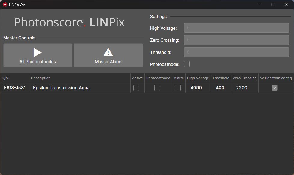
Select Specific Detector.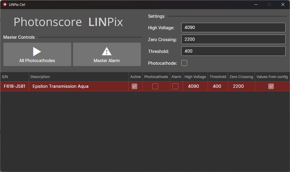
Modify Specific Detector Settings.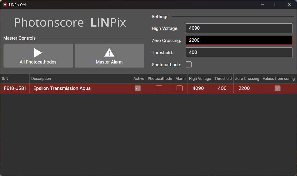
Switching on all Detectors.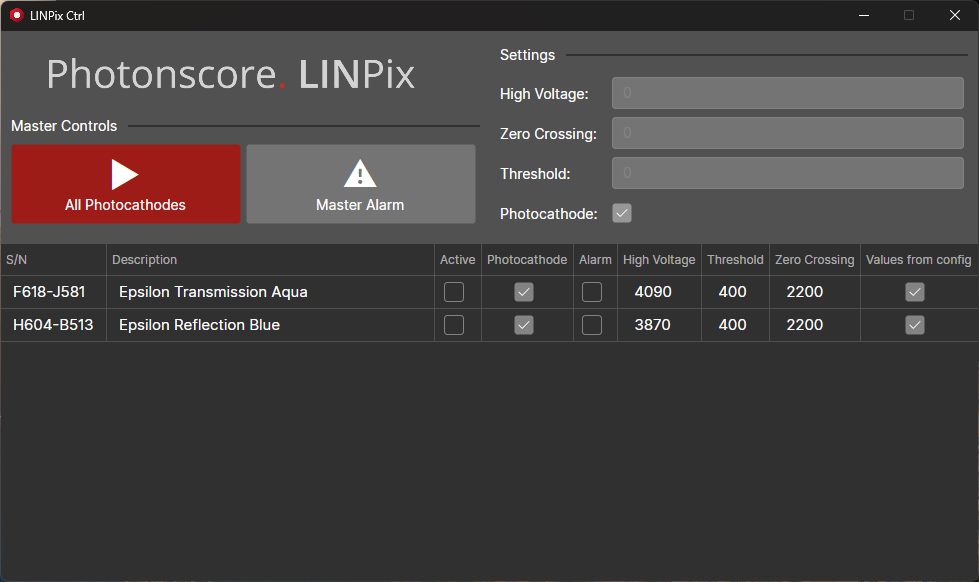
Switching on all Detectors except one.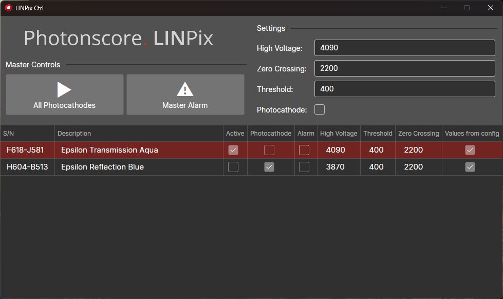
Warning
Please note that the detector's sensitivity may decrease with use. Higher count-rates results in faster degradation and consequently a shorter lifetime of the detector. This is an inherent process and thus photocathode sensitivity degradation and/or MCP gain reduction is not covered by the warranty.
Revision history
| 14 Jan 2025 | Initial revision |
|---|